Leaderboard


Popular Content
Showing content with the highest reputation since 06/05/25 in all areas
-
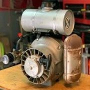
Hey everybody, Hope this post finds you all well, I have been lurking for a little while and watching lots of videos to see what I'd be getting myself into with getting myself a Dodge Conquest/Mitsubishi Starion. Really love their look, flat or wide body. I recently got an 85 Conquest from a friend who had it laying in storage. I like to think it's in pretty good condition and the interior is a real gem. The digital dash is to die for, and there's just something all too charming about the car as a whole. I know that I'm in for some surprises with a 40 year old car, but I'm excited to start. I've studying up as much as I can about the G54B and some common failure points from you guys, and I know I'm in for a very fun ride. The only real issues on it seem to be a head gasket related problem, some minor panel rust on the wheel wells, and some clear-coat separation on the hood. I'm excited to get this thing punched up and looking beautiful. A little about myself: I am a software developer and studied electrical engineering. I live in Texas. New homeowner and starting a family soon (I hope!) I'd like to see myself in manufacturing one day, but programming just seems to pay the bills a little better. I like to program for fun too, I work a lot on signals processing as a matter of hobby and real-time optimizations for graphics rendering, but my heart will always be stuck on seeing something real and physical and I hope to be in a field that'll let me do that before I die. My family used to run a machine shop and I was raised in that, and I miss the days of being able to ask my dad, "Hey, I want to make something..." and he'd show me. Life story aside, I hope to get to continue getting great information and insight from you guys and that I won't try your patience too much when I ask a question or seven. Thanks again!2 points
-
Here's some more pictures. These were kindly taken by my friend who offered me the car. Very excited to get in and do some deep cleaning but, just looking at everything, it really appears to be in fine condition compared to the few I've found around Texas that I could get within my budget and repair-tolerance. Gas tank is definitely first on the list in terms of things. Undercarriage looked great too. He did a wonderful job of keeping this in good of shape as one could for 40 years old when it was his occasional driver. I've scoped out a reasonable budget to make it run, and some overflow to "make it OEM+" (as my mechanic friend puts it). But, first things first is just hitting those common problems as discussed. Thanks for the warm welcome, guys. Here's a picture where you can see the rust on the rear panel wheel well a little more clearly. I'm not too worried about that, all things can be fixed in time.2 points
-
That response has you rebuilding the bottom end ... cleaning the block and putting in new bearings. If you just had a blown head gasket you could literally just pull the head and leave the block in the car and replace the gasket. Depending on the severity of the situation, of course, but that response is more of a total engine rebuild.2 points
-
Congrats and Welcome aboard! 🥳 Let's see some interior pics. I agree that year digital dash and all the sounds it makes are pretty cool! We are here to help you on this journey! P.S. Also an Electrical Engineer here with a title of Controls Engineer. Lots of PLC and Robotic coding for me, among MANY other tasks1 point
-
welcome to the family.it looks like a good starting point.technica nice too.ya the jet valve head is not the best.but dads engine parts can get you a head and everything you need to make it even better.good luck and have fun.1 point
-
Top End Performance in Cali is still offering rebuilding of stock rear struts with 3 choices of strut inserts1 point
-
Just do it. Then report back 😃1 point
-
I love Starquest wheels. One if the few production cars that IMO came eith the perfect set of wheels.1 point
-
Oh, I just realized what I'd used for a prompt. Well, to better answer your question, there is a blown head gasket, but we're using the opportunity to also modify a few things. It's possible the word "rebuild" overstates what I'm actually doing, but we are do have some changes in mind too. Plus the body work, interior restoration, and repaint.1 point
-
Time for another update on the weekend's progress: I think you all probably know that I can't leave things alone, haha. I scuffed up the black epoxy. Some of the filler work I did had pin holes in it (as expected because it was such a quick job), so I used a little glaze putty to fill them. Then reshot with serbia black BC. No clear, for I wanted it to have a more of a satin look to match the rest of the engine compartment. I think it came out good, although I still need to unmask to see how close it really is. I still don't like that corner, but I really need to accept it for what it is...for I'm not going back now. Sprayed the headlight bucket as well, which use to be burgundy. The bracket on the left was bead blasted to bare metal, two coats of epoxy and two coats of BC. The bucket itself was just a quick wipe down and one coat of BC (It's fully hidden but didn't like the burgundy overspray on it) And while I had the spray gun out, I decided to work on my project that was in process prior to the collision..refurishing my spare set of 7/8s. I had these all polished up over the winter but needed the insets painted. I really do wonder if the accident would have ever happened if I had finished this project earlier (with new rear tires on). Really curious to see how these look after removing the tape...I haven't touched them since, just letting the paint cure well.1 point
-
Its always good to get a health check on a engine before disassembly. I at the minimum would want actual oil pressure readings hot at idle and where the bypass is, compression test and leak down test. You will have 1 or 2 cylinders that will give you poor reading do to the HG blown probably but it will let you know the conditions of the rings, cylinders, valves, jet valves, head if cracked. A few minutes can give you a lot of info.1 point
-
Was this just for s**** and giggles or are you really looking into a full rebuild over a blown head gasket? X2 what @techboy suggested. To add to cylinder head inspection, look for any hairline cracks in between valves and sparkplug holes.1 point
-
This week's progress: Got the affected areas of the engine compartment in epoxy primer. The first coat laid a good satin finish, but I added two more coats heavy which resulted in some gloss...typical for the primer I use. Normally this is a good thing, but I was trying to get more of a satin look to match the rest of the compartment. I wanted to get the epoxy nice and thick though such that it does its job. I drive this car, it isn't a garage queen like my other cq, so I want the coatings to be durable. Still debating if I'm going to leave it as-is or lay a thin coat of just Serbia Black base (with no clear). That's as far as I went this weekend because I put my attention on my blue cq and got it going for the season (not bad because I did both of these in the same day). Although, I did compare the core support on it to this car (not sure why I didn't do this prior). In all, I probably should have spent more time on that corner to get it looking a bit closer to stock but I'm not fussing with it anymore at this point. Everything lines up and the repair isn't too obvious.1 point